Moo Machine - Schematic
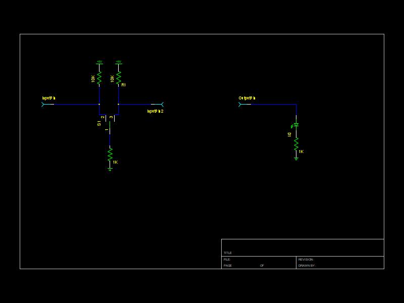
The support circuitry for the Moo Machine is fairly simplistic. The left diagram shows a standard input circuit, which will be replicated nineteen times for each toggle switch. It is a standard pull-up configuration for both sides of the switch.
The output circuits are represented by the right side of the diagram. Those circuits will be replicated 26 times for the various LED outputs for the project.