Moo Machine - Technical Overview
Hardware
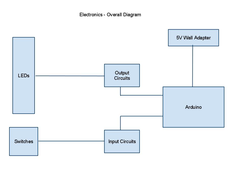
The Moo Machine is based around the Arduino Mega development board. An overview of the electrical components can be located here. The digital input and output pins on the Arduino are all that is necessary for the user interface. The input circuits is a pull-up design, with debouncing logic contained within the code. The outputs are simple LEDs. The Arduino Mega (ATMega 1280) provides enough input and output pins directly for the project.
Software
The editor and interpreter for the Moo Machine is implemented as a single program for the Arduino, writing in Wiring, to implement the Cow programming language The state of the program is kept as a static array for the program code, a static array for the memory, a pointer for the current location in program code, a pointer for the current location in memory, a loop level counter, and a single register. The Cow environment is a modified Harvard architecture, separating the memory space between program instructions and data.
The source code is divided into two main subroutines. The edit subroutine is used to enter programming instructions into the machine by the user. This mode is automatically entered when the Run/Stop switch is in the stop position. While in edit mode, the user is free to toggle the sense switches (0-9), as well as to use the Deposit/Deposit Next, and Examine/Examine Next switches, to enter a program by hand. The reset toggle will reset the program pointer to 0, and reset all memory locations, in preparation of running a program from the beginning. The clear toggle position will clear both the memory and program array, and reset all counters to 0. The save/load toggle is used to load and save programming to the EEPROM, performing a clear before loading the new program.
The interpreter subroutine is activated by toggling the run switch. It is heavily based on the interpreter source code provided at https://github.com/BigZaphod/COW/blob/master/source/cow.cpp. This routine will only perform one instruction at a time, except in the case of loops, where it will perform the full jump. Each instruction is performed until the program counter goes out of the bounds of the entered program. The program will pause for any input operations. Output operations will with pause for user verification if the single-step toggle is activated. Otherwise, a predetermined delay will be inserted into output operations.
Future Ideas
LCD to permit ASCII character display
Ability to easily interact with other devices, such as servos.
Allow the use of the standard Arduino Duemilanove, with shift registers to extend the number of input/outputs pins.
Use of serial output for debugging or programming purposes.